

This guide is a part of Domoticz Tasmota: Control Sonoff without Internet and Yeti Tasmota: Control Sonoff without Internet Instantly which require firmware modification by upgrading official Sonoff firmware to opensource Sonoff Tasmota firmware. By installing Tasmota firmware, We’ll be able to achieve local control of our WiFi Bulb Holder without internet.
Let’s have a look on the whole process briefly. First We’ll prepare our Sonoff Slampher to make it ready for connecting it to our computer. Secondly, We’ll back the original firmware up and upload Sonoff Tasmota firmware using our computer and serial adapter. In last, We’ll configure our new firmware a little bit and our WiFi bulb holder will be ready to be hooked to it’s final place.
Contents:
- Sonoff Slampher Firmware Modification
- – – – Step A – Dissembling
- – – – Step B – Programming Mode
- – – – Step C – Upload Firmware
- – – – Step D – Firmware Configuration
- – – – Step E – Reassembling
- – – – Step F – RF Remote
- – – – – – – – – – – – Pairing
- – – – – – – – – – – – Erase all Paired Buttons
Sonoff Slampher Firmware Modification:
Note: Always unplug the Sonoff device from AC Power Source before start working with it.
Step A – Dissembling:
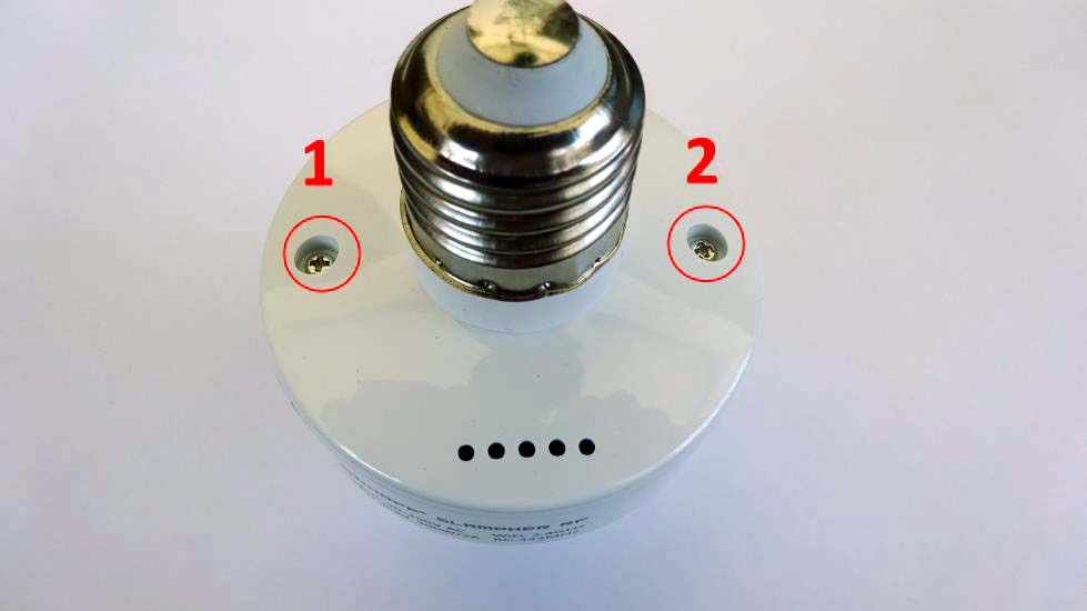
Unscrew the two screws found on the rear side of Sonoff Slampher using screw driver and lift the upper lid. Take the PCB out carefully without pulling the wires connected to it.
Step B – Programming Mode:
Install a male or female header on holes given for programming the device by soldering it permanently for a firm connection. Header without soldering will result in loose connection and uploading may fail.
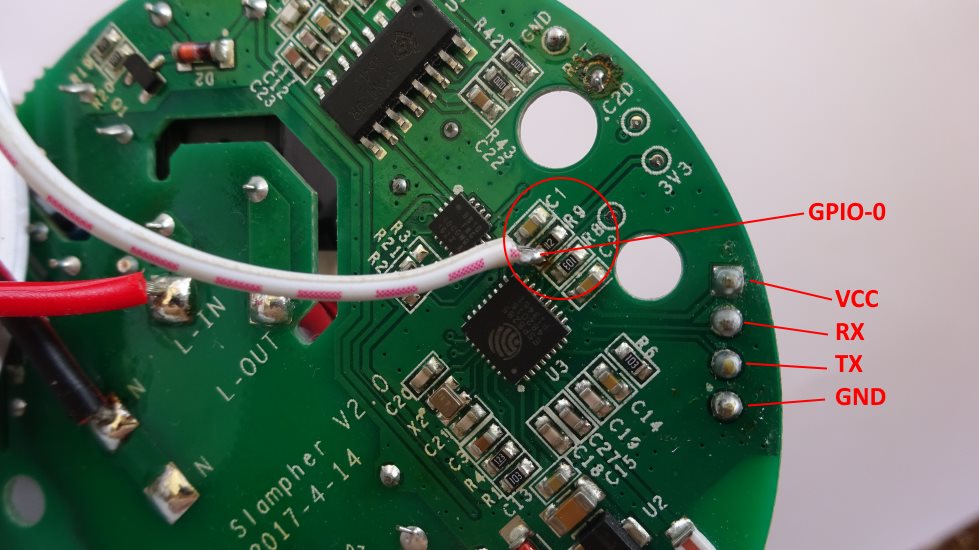
The Sonoff Slampher have an 8bit EFM8BB10F2G-A-QFN20 microcontroller that listens to the radio module messages and handles the on-board button tied to GPIO-0. However, it can not be used to enter Sonoff Slampher into programming mode. For starting Sonoff Slampher in programming mode GPIO-0 should be tied to ground. For this purpose, solder a small piece of wire to ESP8285 side of resistor R9 which is directly connected to GPIO-0.
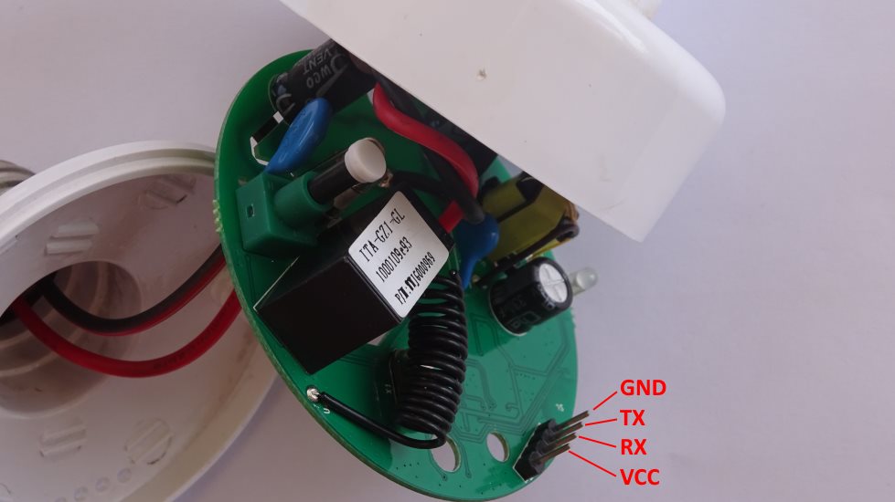
Let’s have a look onto programming header pinout. First pin which is near the 3V3 printed on PCB, is VCC followed by RX, TX and GND. Connect FTDI according to the following combinations.
| FTDI | Sonoff Slampher |
| 3.3V | VCC |
| TX | RX |
| RX | TX |
| GND | GND |

Connect the wire solder on resistor R9, to GND and Plug the FTDI in to PC. Now micro-controller present in our Sonoff Slampher i.e. ESP8285 will start in programming mode.
Step C – Upload Firmware:
Backup official firmware by following our guide Backup & Restore Official Firmware of Sonoff WiFi Smart Switches under Backup / Download Official Firmware section. After backup, download Sonoff-Tasmota Firmware and upload it according to Upload Official / Third Party Firmware.
Step D – Firmware Configuration:
By short pressing on board button four times, Sonoff Tasmota Firmware allows booting up Sonoff Smart Switches into Wifi Manager Mode providing an Access Point with IP address 192.168.4.1 to configure WiFi credentials. However, the case is different with Sonoff Slampher. As we already know that 8bit EFM8BB10F2G-A-QFN20 microcontroller handles the on-board button tied to GPIO-0, so we cannot start Sonoff Slampher into pairing mode by pressing on board button.
Note: Do not plug Sonoff Device to AC Power Source
During firmware upgrade, we started Sonoff Slampher into programming mode using a short wire connecting resistor R9 and GND. The very same procedure will be followed here to boot the slampher in to WiFi Manager Mode. Touch the wire to GND four times quickly and repeatedly and Sonoff Slampher will boot into Wifi Manager Mode.
Now a new Access Point will pop up under available WiFi networks with the name of sonoff-XXXX (Where XXXX is any number). Connect to this new sonoff-XXXX network and configuration page will open in your browser. If it does not open into your browser automatically, open to http://192.168.4.1 into your favourite browser.
Connect Sonoff Slampher to your WiFi network according to Configure WiFi Network Settings under Sonoff Tasmota Firmware and configure MQTT parameters by following the instructions given under Configure MQTT Settings under Sonoff Tasmota Firmware. Now Sonoff Slampher can be accessed by visiting the IP address assigned to it by your WiFi router. Consult your router documentation on how to find the IP address of connected devices. You can also assign a static IP address to your Sonoff device by following instruction given under Set Static IP Address under Sonoff Tasmota Firmware section. By default web page access to Sonoff Tasmota Firmware is open and anyone connected to WiFi network can access to it. Let’s secure web access page by setting up Web Admin Password according to Configure Web Admin Password under Sonoff Tasmota Firmware. Change the module type according to Configure Module Type under Sonoff Tasmota Firmware otherwise Sonoff Slampher may not work as expected.
Now You have completed almost all necessary configuration of Sonoff Tasmota. You can also set default Power on State which will be followed on Sonoff device restart, among ON, OFF and KEEP according to Configure Power On State After Boot Up. Correct Timezone and NTP Server configurations are necessary for timer related functions. However, It is recommended to configure NTP Server and Timezone according to instructions given in Configure NTP Server and Timezone.
Step E – Reassembling:
Now our Sonoff Slampher is ready for the work. Desolder the wire connected to resistor R9 carefully. Reassemble Sonoff Slampher by sliding the PCB inside the enclosure taking care of push button correctly placing in it’s hole. Now put on the lid and tighten the screws back. Plug the Sonoff Slampher into socket and voila!!. You can toggle the light ON & OFF by visiting the IP address assigned to Sonoff Slampher by router. But the smarter way to toggle a switch is discussed in our guide Domoticz Tasmota: Control Sonoff without Internet. Navigate to Step E – Connect & Control the devices to proceed further if you are already following the steps in our guide Domoticz Tasmota: Control Sonoff without Internet.
Step F – RF Remote:
Pairing:
Quickly press the Sonoff Slampher button twice. Red LED will blink once which means Sonoff Slampher is ready for pairing RF Remote. Press and hold desired RF Remote button for couple of seconds and particular RF Remote button will be paired with Sonoff Slampher. Now you can use the RF remote to switch the Slampher ON and OFF as desired.
Erase all Paired Buttons:
Quickly press the Sonoff Slampher button thrice. Red LED will be turned ON for few seconds and known RF code will be erased.
Now you can also control your Sonoff S20 directly using Yeti Smart Phone app. There is no need to establish your own Raspberry Pi server as Yeti connects to your Sonoff S20 directly using WiFi network. Follow our guide Yeti Tasmota: Control Sonoff without Internet Instantly for step by step procedure.
Hi,
I’d like to ask where is the other end of soldered wire from R9 going to? Is it going to the GND of FTDI, GND of the four flashing pins (VCC, RX, TX, GND), or is it going to GND near C20 / R22 ? Thank you very much!
Dear Hoedha,
Connect other end of wire to GND (obviously FTDI & Sonoff Slampher both have common GND) and power up the device to start in programming mode.
Hi. Thanks for posting this. I put this together yesterday and could not get esptool to connect. I’m guessing that it was not seeing GPIO-0 tied to ground. I made the connection you illustrated with R9 on the chip side and tied to ground at the header pins I soldered on. I test continuity from the other side of the resistor and the header ground and it indeed was connected. I checked voltage at the header pins and had about 3.2V . I double check TX->RX and RX->TX and even reversed them to be safe and it still did not… Read more »
Reboot the slampher while keeping gpio0 connected to ground, so that it boots into programming mode.
Right. I thought that’s what I was doing. How do I reboot it?
Plug the FTDI in your pc after connecting gpio0 to GND.
Thanks for the help. I certainly think that’s what I’m doing. I have GPIO0 wired to ground via a soldered connection. I plug in the FTDI and then use esptool to send the code. That’s what I should be doing, right?
Yes
Ok.. That’s what I’m doing but it does not appear to be going into programming mode.
We cannot figure it out this way. Better is, Read this post carefully once again. Check your cables & connections. Check if your FTDI is set to 3.3v logic and is working.
@chuck, you say you have a soldered connection between R9 and gnd. Do you separate R9 from Gnd after the reboot?
Random, You must disconnect R9 and GND after flashing the firmware, otherwise your Sonoff will boot in programming mode all the times.
Do you know if it is possible to decouple relay operation from RF signal. I think in tasmota for exmaple in a configuration with a button you can have two toppics realy and button so pressing button does not switch the realy. Do you know if such a thing would be possible with this device?
You can use rules and commands in Tasmota to achieve your desired functionality.
Thank you. That is what I suspected just wanted confirmation before going down that route
https://community.home-assistant.io/t/sonoff-slampher-and-pir-coordination-of-2-seperate-units/147885
I have a solution for this…
I did what you wrote, when I connect the Slampher, the LED shines red (no blinking) and when I run
sudo esptool.py write_flash --flash_size 1MB --flash_mode dout 0x0 sonoff-6.5.0.binI get
Wrote 519920 bytes (355646 compressed) at 0x00000000 in 31.5 seconds (effective 132.2 kbit/s)...File md5: 2f556aa0f8ebdaaf715ae64ec7db63ce
Flash md5: d709f08010919735c15d8eb690088555
MD5 of 0xFF is 7857d474b2c0351330e391578eda662f
A fatal error occurred: MD5 of file does not match data in flash!
It seems I can’t overwrite the firmware.
Erase the flash memory
esptool.py --port COM5 erase_flashbefore uploading the new binary file. Change the port accordingly. Download the firmware file once again. Have a look on to Backup & Restore Official Firmware of Sonoff WiFi Smart Switches for more information.Thanks for the tutorial, very easy to follow. I tried soldering the wire to resistor 9 and pulled the solder pad up. That trace doesn’t go anywhere, so the device still works. In the end, I put all of my Slamphers into programming mode by holding a short wire between R9 and GND while plugging it in. Although this is fiddly, I’d argue that it’s less fiddly than soldering to an SMC pad with hot clumsy soldering irons. Might I suggest that you add this to your tutorial? That is, suggest to just hold a wire in place if SMC… Read more »
Slampher pairing instruction is wrong.
Press button until red light flashes once to set pairing mode.
Press button until red light flashes twice to delete pairing.
So the layout has changed some in version 2.4 The r9 resistor is in a different place. I haven’t been successful in getting it in programming mode. I’m wondering if someone can help me out if I upload an image?
https://photos.app.goo.gl/g5wGMEffVcwvCWHE6
I think I see an unpopulated path for GPI0
Hey, I had the same problem and just solved it. Following the traces on the board shows that GPIO0 still leads to a resistor named R9 though in a different location. I tried shorting that to ground to get into programming mode, I think I succeeded a couple of times, but in the end on my final attempt I shorted directly to the ESP8285 chip (I haven’t soldered anything, I simply held a wire against the pin, since you only need to short it when it boots up). The 2nd pin along the bottom is GPIO0 as shown here https://www.espressif.com/sites/default/files/0a-esp8285_datasheet_en_v1.0_20160422.pdf… Read more »
I was looking at my board and I see that the chip side of r9 goes to 2nd pin in on the bottom of the esp chip. In your photo I see it is the trace that goes under the printed U3? Try shorting on that same pin or see where the trace goes on the other side of the board?
These instructions are out of date as of today (August 5, 2020). I just had to hold the button on the Slampher down and power up the programmer. The LED blinks red and turns off indicating it is in programmable mode. Upload the latest tasmota and do the rest of the setup (connecting to wifi captive portal and adding WiFi SSID/Password).
No need to connect R9 to GND or anything fancy. That doesn’t work in fact.