
ESP8266, NodeMCU and WeMos etc. development boards are very popular among IOT enthusiast. But as noobs, certain mistakes are made which produce unwanted results. In this particular post, We’ll discuss these problems gradually and their possible solutions. Feedback is much appreciated.
Contents:
- Using Arduino IDE for programming Nodemcu
- Pin number confusions
- Defining INPUT, OUTPUT and INTERRUPT pins
Using Arduino IDE for programming Nodemcu:
Arduino IDE does not support ESP8266 microcontroller units which is the heart of Nodemcu development boards. Arduino core for ESP8266 WiFi chip needs to be installed as following;
- Install Arduino 1.8.2 from the Arduino website
- Start Arduino and open Preferences window
- Enter http://arduino.esp8266.com/stable/package_esp8266com_index.json into Additional Board Manager URLs field
- Open Boards Manager from Tools > Board menu and install esp8266 platform (and don’t forget to select your ESP8266 board from Tools > Board menu after installation).
Pin number confusions:
ESP8266 pinout diagram represents pins numbers as GPIOXX (Where XX is any number). On development boards such as NodeMCU or WeMos, pin numbers are written as D0, D1, D2 and so on. These are not the actual pin numbers of microcontroller unit present on this development board i.e. ESP8266.
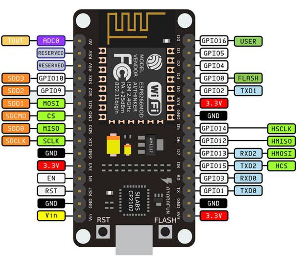
D0 is actually GPIO16, D1 is GPIO5, D2 is GPIO4 and so on. Let’s suppose, We have attached an LED on pin D1 on NodeMCU development board, so in our sketch, We’ll use int ledPin = 5;. By using actuall MCU pin numbers, We’ll never have any pin maping related problems.
Defining INPUT, OUTPUT and INTERRUPT pins:
GPIO5 (D1), GPIO4 (D2), GPIO14 (D5), GPIO12 (D6), GPIO13 (D7) can be used as INPUT or OUTPUT and supports INTERRUPTS. GPIO16 (D0) does not support interrupts and is tied to RST (Reset) pin using low value resistor (330 – 1000 ohm) to wake up the mcu from Deepsleep.
Using GPIO0 (D3), GPIO2 (D4) and GPIO15 (D8) can be bit tricky. There are certain reasons, for example, GPIO0 (D3) and GPIO2 (D4) are pulled HIGH (PULL-UP Resistor) for normal start up of ESP8266 while GPIO15 (D8) is pulled LOW (PULL-DOWN Resistor). It is recommended to not use these pins as INPUT.
I2C & PWM:
All pins on NodeMCU (ESP8266) are capable of I2C and PWM except GPIO16 (D0). One can change I2C pins using Wire library as following.
Wire.begin(0,2); //sda=0 | D3, scl=2 | D4
Where “0” is SDA pin and “2” is SCL pin.
Analog Pin:
ESP8266 can take up to 1V on analog pin i.e. 1V outputs a value of 1023/1024 while NodeMCU has a voltage divider on the A0 pin and can handle up to 3.3V.
Attaching Devices with 5v Logic:
NodeMCU (ESP8266) is a 3.3V device and should not be coupled with any 5V logic devices. All the pins can tolerate 5V for shorter period of time except TX and RX pins. Logic Level Converters are available for connecting 5v devices with NodeMCU or ESP8266.
Further Reading:
-
Wake ESP8266 by input signals during Deep Sleep the same way as Pin Change Interrupts
-
ESPMetRED an Arduino IDE compatible library to communicate ESP8266 and Node-Red via MQTT