
ESP8266 is very popular among IOT enthusiasts due to it’s builtin WiFi capabilities which keep our Fun Gadgets connected together. Normally it draws 215 mA current during data transmission and 0.9 mA are consumed during idle conditions when ESP8266 is not doing anything for us except keeping itself connected to our WiFi network. It’s Deep Sleep function is superb with 60 µA current consumption which is suitable in our Battery Powered Projects such as Weather Station, where it is required to take few readings during day or night and send them to the server and rest of time, ESP8266 keep itself under deep sleeps.
Sometimes, We require publishing some sort of output to our server and battery is only option to power our project. As ESP8266 does not support interrupts during deep sleep, how can We accomplish this task under this particular scenario?
Here, is a workaround, using couple of simple electronic components along with CH_PD, our ESP8266 will respond back to us even during deep sleep. Normally Reset, CH_PD, GPIO-0 and GPIO-2 are pulled up using 10 K resistors and GPIO-15 is pulled down the same way. But here we’ll pull CH_PD pin down using 10 K resistor.
Let’s suppose we have a Push Button attached to our Battery Powered ESP8266 and we want to publish it’s state to our server which is then proceeded to switch a relay connected to some other ESP8266.
NOTE: THIS METHOD WILL ONLY WORK WITH BARE ESP8266 MODEULE. IT WILL NOT WORK WITH ANY OF DEVELOPMENT BOARDS SUCH AS NODEMCU ETC.
Circuit Diagram:
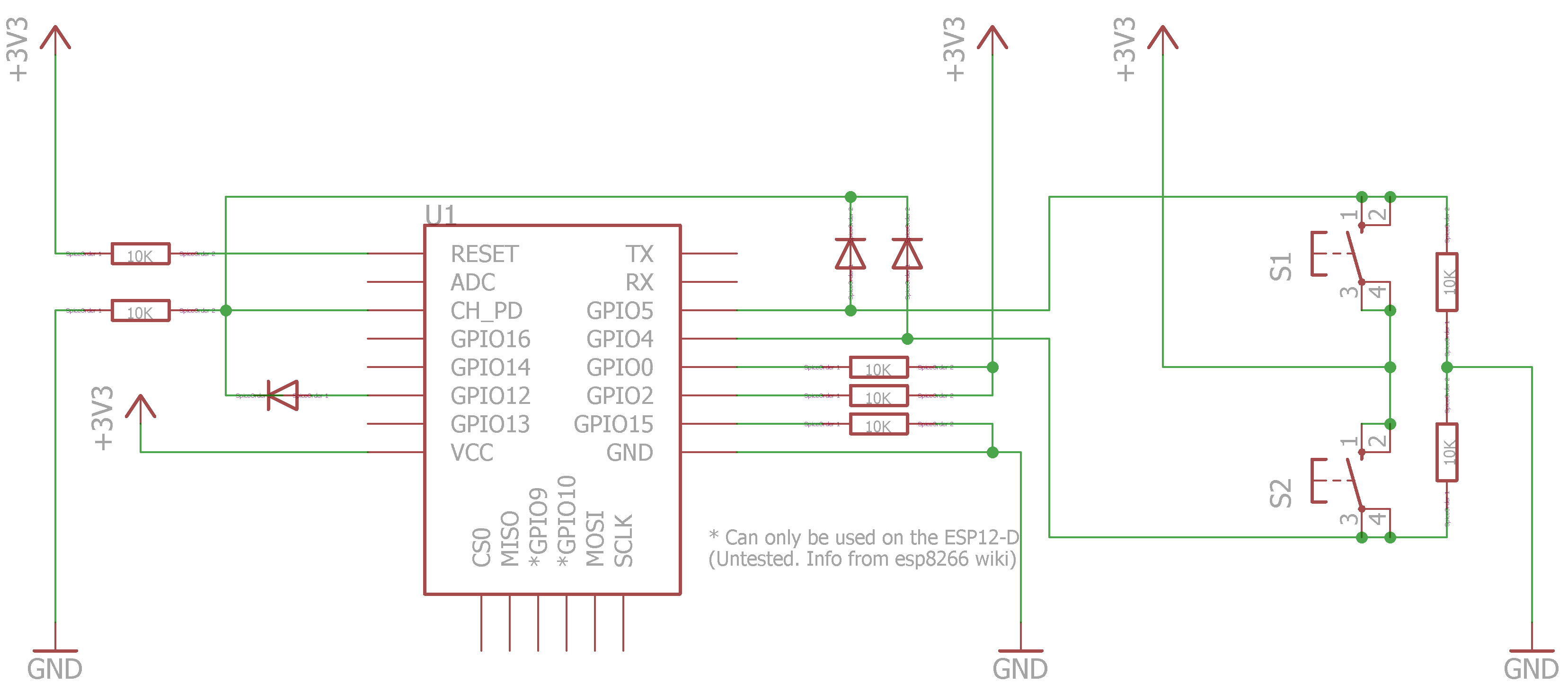
- Connect one side of Push Button to VCC and other side to a GPIO let’s suppose GPIO-4
- GPIO side of Push Button is pulled down using 10 K resistor
- Using a diode, GPIO is connected to CH_PD pin of ESP8266
- An other GPIO such as GPIO-12 is also connected to CH_PD using a diode in the same way.
When Push Button is pressed, It pulls CH_PD to HIGH which switches ESP8266 ON. In the mean time, other GPIO (GPIO-12, as supposed earlier) connected to CH_PD is defined as OUTPUT and switched to HIGH as early as possible in setup() function. ESP8266 boots up, waits for connection to server, publish the output and check for Push Button to be released. As soon as Button is released and information is published to server already, ESP8266 switches GPIO (GPIO-12, as supposed earlier) from HIGH to LOW and ESP8266 switches to OFF.
There are two Push Buttons attached to ESP8266 (at GPIO-5 and GPIO-4) in schematics shown above. ESP8266 responds to both of buttons in same manner identifies them individually. Here is an example sketch which uses ESPMetRED Library for communicating ESP8266 to Node-Red.
Example Sketch:
#include <ESPMetRED.h>

const char* MQTT_PUBLISH_TOPIC = "ESPBATTBUTTON/OUT";
const char* MQTT_SUBSCRIBE_TOPIC = "ESPBATTBUTTON/IN";
const char* CLIENT_ID = "ESPBATTBUTTON";
const char* WIFI_SSID = "Ahmed";
const char* WIFI_PASSWORD = "WiFI Password";
const char* MQTT_SERVER = "192.168.50.30";
const char* MQTT_USER = "pi";
const char* MQTT_PASSWORD = "MQTT Password";

IPAddress ip(192, 168, 50, 40);
IPAddress gateway(192, 168, 50, 1);
IPAddress subnet(255, 255, 255, 0);
IPAddress dns(192, 168, 50, 1);

ESPMetRED client(ip, gateway, subnet, dns); //starting library with fixed IP

int buttons[2] = {4, 5}; // Pins on which buttons are attached
int button;              // Variable to store the button which triggered the bootup
int wake = 12;           // Pin which is used to Keep ESP awake until job is finished

boolean published = false;
boolean notified = false;

void setup() {

// ESP Awake Pin, the pin which keeps CH_PD HIGH, a requirement for normal functioning of ESP8266
  pinMode(wake, OUTPUT);
  digitalWrite(wake, HIGH);


//Check which button was pressed

  for(int i=0; i<2; i++)
  {
    pinMode(buttons[i], INPUT);
    if(digitalRead(buttons[i]) == HIGH)
    {
      button = buttons[i];
      return; //Push Button identified, Leave the loop
    }
  }
}

void loop() {
  client.keepalive(); // Necessary for successful connection between server and client

  if((client.stMqTT()) && (!published)) // stMqTT() function returns the MQTT connection state
  {
    published = true;
    client.Publish("debug", client.JsonString(String(CLIENT_ID), String(button))); //Publish the data about Pushed Button
  }

  if((published) && (digitalRead(button) == HIGH)) // Check if button is released, a debounce step
  {
    if(!notified) // Notify the server that Button is not yet released
    {
      notified = true;
      client.Publish("debug", String(CLIENT_ID) + " [ESP Waiting Release of Button]");
    }
  }
  else if((published) && (digitalRead(button) == LOW)) //Push Button has released, Let's get switched OFF
  {
    client.Publish("debug", String(CLIENT_ID) + " [ESP's Going DOWN]");
    digitalWrite(wake, LOW); //Turns the ESP OFF
  }
}
Example Sketch Lite-I:
/*
	*	Two Push buttons are attached to GPIO 4 & 5
	*	GPIO 12 keeps the CH_PD HIGH
	*	ESP8266 goes to Sleep by switching GPIO 12 to LOW
*/

int buttons[2] = {4, 5}; // Pins on which buttons are attached
int button;              // Variable to store the button which triggered the bootup
int wake = 12;           // Pin which is used to Keep ESP awake until job is finished

void setup() {

// ESP Awake Pin, the pin which keeps CH_PD HIGH, a requirement for normal functioning of ESP8266
  pinMode(wake, OUTPUT);
  digitalWrite(wake, HIGH);


//Check which button was pressed

  for(int i=0; i<2; i++)
  {
    pinMode(buttons[i], INPUT);
    if(digitalRead(buttons[i]) == HIGH)
    {
      button = buttons[i];
      return; //Push Button identified, Leave the loop
    }
  }

  // do whatever you want before returning ESP8266 back to sleep

  digitalWrite(wake, LOW); //Turns the ESP OFF
}

void loop() {

}
Example Sketch Lite-II:
/*
	*	Push buttons is attached to GPIO 4
	*	GPIO 12 keeps the CH_PD HIGH
	*	ESP8266 goes to Sleep by switching GPIO 12 to LOW
*/

int button = 4; // Pin on which button is attached
int wake = 12;           // Pin which is used to Keep ESP awake until job is finished

void setup() {

// ESP Awake Pin, the pin which keeps CH_PD HIGH, a requirement for normal functioning of ESP8266
  pinMode(wake, OUTPUT);
  digitalWrite(wake, HIGH);

// do whatever you want before returning ESP8266 back to sleep

  digitalWrite(wake, LOW); //Turns the ESP OFF
}

void loop() {

}
Hi Ahmed. Nice post. Can you please post a diagram of the circuit? I would like to try it out as a door alarm switch but I want to make sure I have the correct circuit.
Thank you so much Jason for the compliments and pointing out the corrections needed. Actually, there were some technical issues with the post and circuit diagram was not visible. Please check it now.
for some reasons it’s not possible to view the circuit or code even after giving the like
There was an issue with plugin. I have disabled it now. Please check it.
I’m curious why, in the setup, your for() loop steps through 4 tries even though there are only two pins that you’re checking.
It was a typo which is now corrected!!. Thank you so much for the identification.
I have implemented practically this exact project. It’s beautifully simple. Only change required is that my esp8266 has an internal pullup on CH_PD and the external 10k pulldown would not overcome it. I paralleled 2 10k’s (for 5k) and works fine.
Thank you.
I think you are using a development board. Always use bare ESP8266 module in these kind of projects to save power. Because voltage regulators and serial converters mounted over development boards will always consume power even your ESP8266 is turned off.
Hi i would like to do a similar setup with a reed switch, so when the magnet is pulled away from the reed swith, wemos would wake up , connect to wifi and send message. can u please tell me how to setup my circuit. I dont want to use MQTT, i will be using blynk software. let me know please. Thanks
Hello Ravil. Use Example Sketch Lite-I or Example Sketch Lite-II with Normally Closed Reed Switch.
Thank you for sharing this.
A couple of questions, if I may:
a) I read somewhere that the ESP8266, after entering deepsleep, will wake up if RST receives a HIGH pulse. Wouldn’t this be easier?
b) From what I read, the ESP8266 can take up tp 300ms to boot. How could I then detect a shorter button-press than 300ms?
It’s different that ESP Deep Sleep you are referring in your comment. Please read the details thoroughly. In this setup CH_PD pin is pulsed HIGH by switch which starts up the ESP module. After bootup CH_PD pin is kept HIGH by another GPIO Pins. ESP performs your required operation and that particular GPIO is switched to LOW and ESP again goes to sleep. Purpose of this kind of setup is to wake ESP from external interrupt during deep sleep, as ESP does not support wake up from external interrupts. As far as your question about 300ms boot time is concerned,… Read more »
Why can’t just a GND pulse on RST pin be used to wake up the ESP?
This setup is more advanced and you can use multiple buttons by adopting it. In your described case only one button can be attached.
What software have you used to create this circuit diagram?
Eagle CAD
Thanks dude!
Thanks for the great solution to the wake up on button. Works on Adafruit HAZZAH Feather board, if you remove the CH_PD connection during code uploads. Positive waves.
Seems like what I was searching! But before trying this out: Your circuit doesn’t show wiring for programming the ESP8266. Can the (blank) ESP8266 be programmed the ‘normal’ way with esptool.py (and how to set it in programming mode)?
Thanks, Rob.
Q: I see no wiring for programming. Since the pull down of CH-PD goes programming ‘ normally’ with esptool.py, or is something special needed?
Thanks, Rob.
Yes. This schematic cannot be used to program the ESP. Pull CH_PD high using 10K resistor and tie GPIO0 to GND and power it up, ESP will boot into programming mode.
Thanks, I’ll give it a try then!
Hi, thanks for this post it is very helpful!
I would like to ask if it’s also possible have deep sleep wake as well and tie GPIO16 to RESET? Is there a circuit that can allow both wake on GPIO, as well as deep sleep?
Dear Alex,
There would be no simple way to achieve both of functionalities together. As we are using the magic of CH_PD pin which should be pulled HIGH using 10K resistor in case of normal wake up from deepsleep and here we have pulled it LOW to keep our ESP8266 down to save power. You may use ATTiny85 incorporated in this setup to achieve both of your goals.
I believe that sleep could be used to to power-down Ahmed’s setup and even power-up. But that would mean having to leave CH_PD high, defeating the power saving of having the ESP off. Even worse this would consume .33mA more through the 10K resistor. The sleep command and interrupt wake function would need to not mess with the line ” digitalWrite(wake, LOW); //Turns the ESP OFF”. Then once conditions don’t require the wake from deep sleep, then trigger the CH_PD power down. So in effect this would give two modes of powering down, each with different power consumption. Ahmed’s Off-mode… Read more »
So, what was the current consumption this way?
Current consumption should be lesser than deepsleep mode. Have to calculate it using Multimeter.
What diode you put there?
You can use any of the following;
https://hobbytronics.pk/product/1n4007-1a-1000v-rectifier-diode/
https://hobbytronics.pk/product/1n4148-smd-diode/
Hi, I tried this setup using the Adafruit HUZZAH ESP8266 Breakout, which has a ESP-12S module embedded in the board. I removed the external 10 k pull-up resistor that was soldered in the board and tried the code but it didn’t work properly. I measured the resistance between the 3V pin and the EN pin and obtained 12 kOHM. Did you test the code in a ESP-12S board? Which suggestion can you give me?
Some tested in nodemcu esp8266 lolin? Could you share me the way that i have to wire the components? I am new in arduino, Thanks in advance
Victor, it only works with bare ESP8266 module. It will not work with Nodemcu or any other development board.
In all development boards, CH_PD pin is always pulled HIGH while here in this particular setup, we are using CH_PD pin (Pulled HIGH) to wake up or sleep (Pulled LOW) the ESP8266.
Thanks, any model un particular? I have a esp 01, this could work in the esp01? Excuses I am new in that topic
Yes. It will work with ESP 01 or any other modules (except development boards such as nodemcu). In some module control pin is named as CH_PD while in others it is named as EN. Both are the same pins.
Hello again, i was trying for several days with a esp01, but it does not work, I was trying with a reed switch and the button, please could you help me with the diagram, that i am trying is when the reed swith is open i want to send a message by http and later turn off the ESP01, later when the reed swith is closed the ESP0 must be turn on, send a http message then turn off. My real problem is that i dont know how to wiring the components.
Thanks for ypur help.
Great proposal !